Rollers are among the most mechanically demanding components in industrial production — they must maintain precise geometry under continuous load, resist surface fatigue across millions of cycles, and hold dimensional tolerances that directly determine the performance of the systems they serve. Whether the application is a printing press, a steel rolling mill, a paper machine, a textile calender, or a conveyor system, the quality of the roller begins and ends with the machine used to process it. CNC roller processing machines have become the production standard precisely because manual or conventional machining cannot consistently deliver the surface finish, dimensional accuracy, and geometric correctness that modern roller applications demand. This article examines how these machines work, what configurations exist, what specifications matter, and how to approach the selection process with the clarity that a significant capital investment deserves.
Content
A CNC roller processing machine is a purpose-built or heavily adapted CNC machine tool designed to perform one or more operations on cylindrical roller workpieces — typically turning, grinding, milling, drilling, knurling, or some combination of these — under computer numerical control. The defining challenge of roller processing is the combination of large workpiece size, high length-to-diameter ratios, demanding surface finish requirements, and tight geometric tolerances (cylindricity, straightness, and runout) that must be maintained across the full roller length.
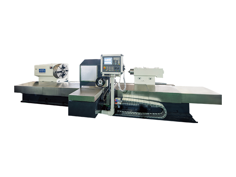
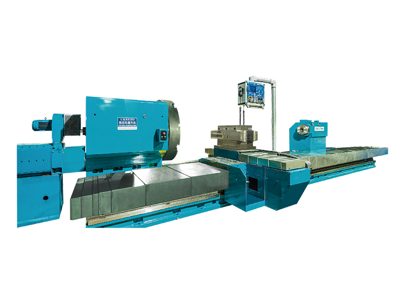
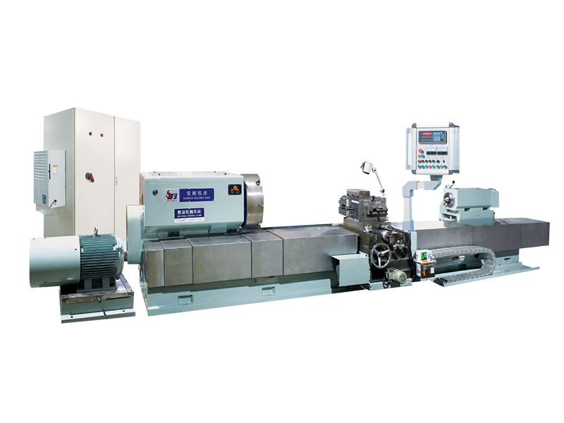
Standard CNC lathes and machining centers can handle small rollers, but dedicated roller processing machines incorporate features specifically addressing the structural and geometric challenges of long, heavy cylindrical workpieces: extended bed lengths, heavy-duty steady rests spaced along the workpiece length, high-rigidity headstocks and tailstocks designed for large bearing loads, and in-process gauging systems that measure the workpiece during cutting or grinding and feed corrections back to the CNC controller in real time. The result is a machine capable of processing rollers ranging from a few hundred millimeters to several meters in length, from a few kilograms to many tons in weight, and to surface finish values and dimensional tolerances that manual methods cannot reliably approach.
The category of CNC roller processing machines encompasses several distinct machine types, each optimized for a different stage of the roller manufacturing process or a different class of roller application.
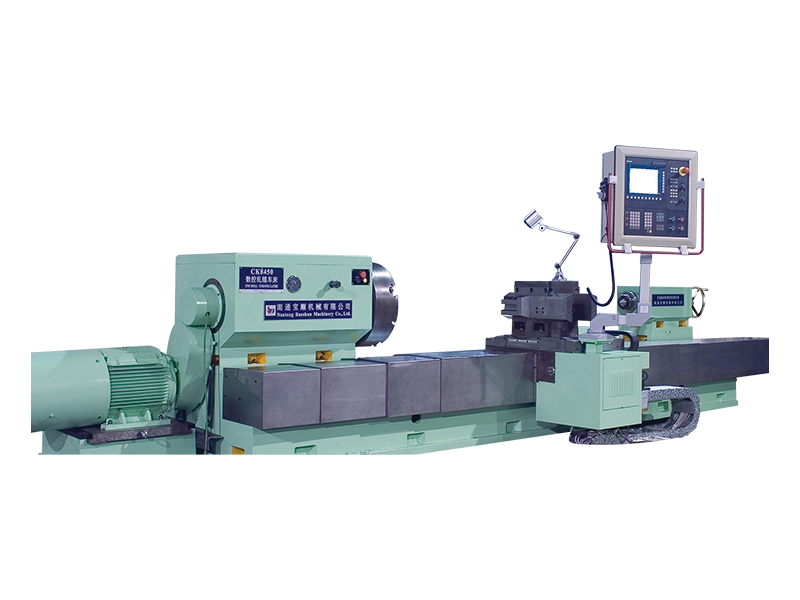
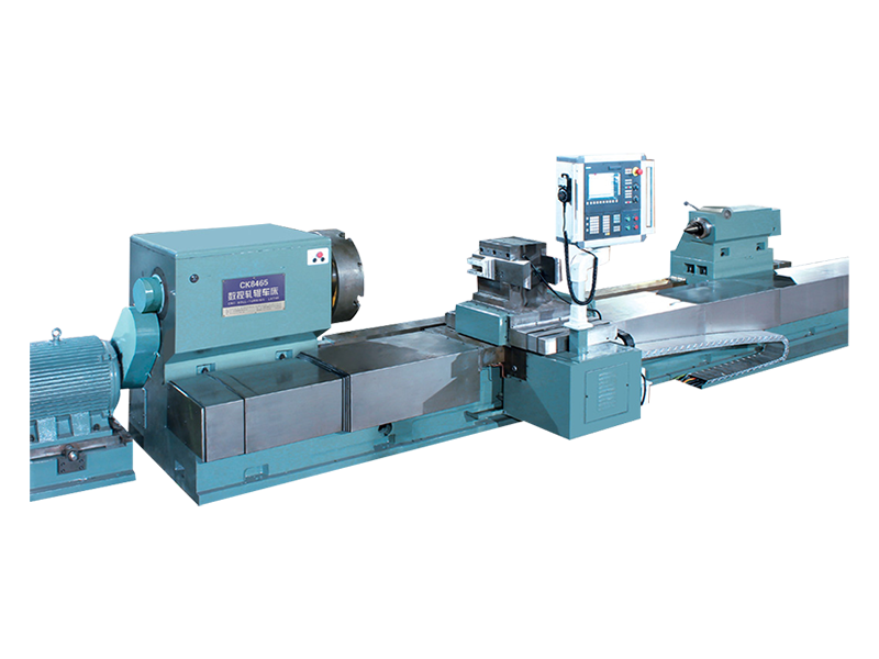
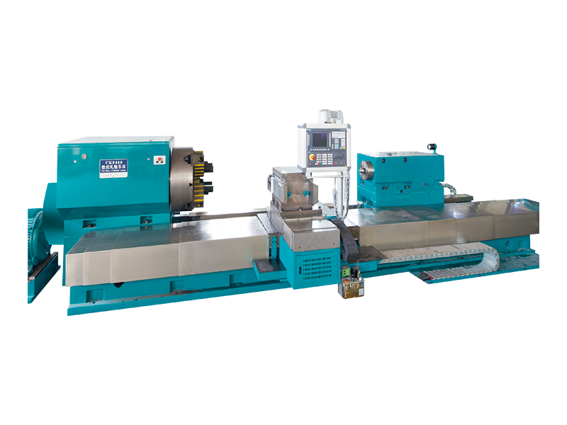
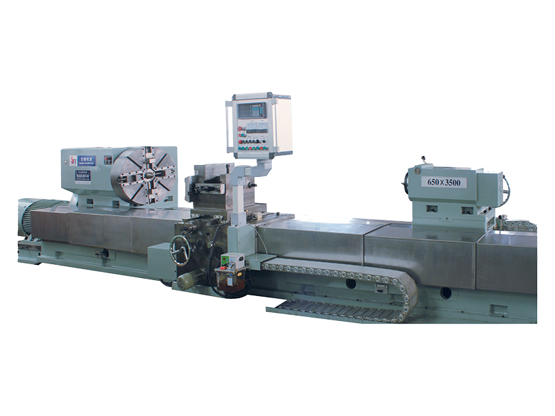
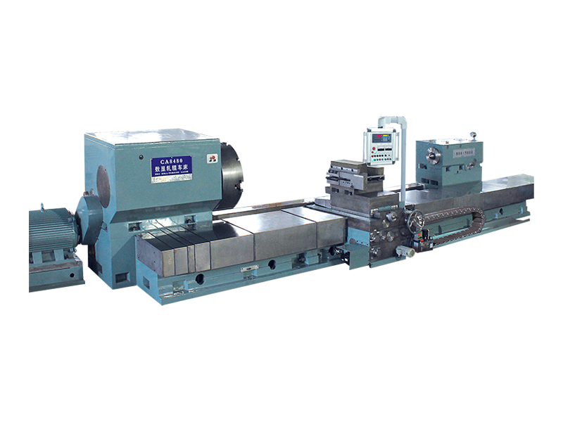
Roll turning lathes are the primary roughing and semi-finishing machines in roller production. They remove large amounts of material from forged or cast roller blanks, establishing the basic geometry — diameter, crown profile, journal dimensions, and shoulder transitions — before the workpiece moves to grinding. CNC roll turning lathes for industrial rollers are typically configured as heavy-duty horizontal lathes with bed lengths from 3 to 20 meters, swing diameters from 600mm to over 2,000mm, and spindle torques measured in tens of thousands of newton-meters. The CNC system controls the coordinated motion of the carriage along the bed (Z axis) and the cross-slide perpendicular to the spindle axis (X axis), enabling complex crown profiles and tapered sections to be turned in a single pass without manual template following.
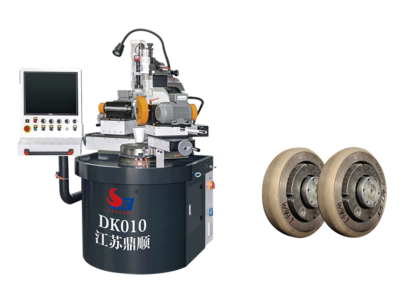
Roll grinding is the finishing operation that determines the final surface quality and dimensional accuracy of the roller. CNC roll grinding machines use abrasive grinding wheels — rather than cutting tools — traversing the roller's surface to remove precise amounts of material, typically in the range of micrometers per pass. The CNC system controls the grinding wheel's position and feed rate with sub-micron resolution, allowing the machine to produce cylindrical rollers with surface roughness values below Ra 0.1 µm and geometric tolerances (cylindricity and runout) below 1 µm on precision applications. In-process gauging, where a measuring probe contacts the roller surface during grinding and feeds dimensional data back to the controller for automatic compensation, is standard on modern CNC roll grinding machines and is what makes sub-micron tolerance production achievable in a production environment.
Some roller applications require surface textures, patterns, or relief features machined into the roller surface — embossing rollers for packaging, engraved rollers for textile printing, and structured rollers for optical film production are examples. CNC roll milling and engraving machines add a rotating milling or engraving spindle to the basic roll turning configuration, with the CNC system coordinating the spindle rotation (C axis), the carriage traverse (Z axis), the cross-slide (X axis), and sometimes the tool spindle orientation (B axis) to produce helical, circumferential, or complex three-dimensional surface patterns on the roller body.
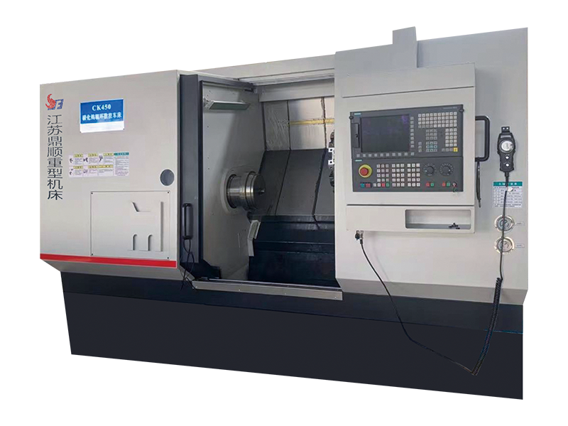
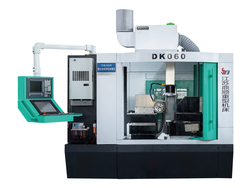
The most capable — and most expensive — category integrates turning, milling, drilling, and sometimes grinding capability in a single machine with automatic tool changing. These CNC roll processing centers allow complete roller machining from rough blank to finished workpiece in a single setup, eliminating the positioning errors and setup time that accumulate when a roller must be transferred between multiple dedicated machines. For precision rollers where geometric accuracy is paramount, minimizing setup changes directly improves final part quality.
| Specification | What It Determines | Typical Range |
| Swing Over Bed | Maximum roller diameter that can be processed | 400mm – 3,000mm |
| Distance Between Centers | Maximum roller length that can be processed | 1m – 20m |
| Spindle Torque | Maximum cutting force sustainable during turning | 5 kNm – 100 kNm |
| Positioning Resolution | Minimum incremental move on each axis | 0.1µm – 1µm |
| Achievable Surface Roughness | Final roller surface finish capability | Ra 0.05µm – Ra 3.2µm |
| Steady Rest Capacity | Maximum workpiece weight supportable between centers | 500 kg – 100 t |
| In-Process Gauging | Real-time dimensional feedback during machining | Standard on precision grinders |
Steady rests are one of the most mechanically critical elements of any CNC roller processing machine, and their design quality has a direct and measurable impact on the geometric accuracy of finished rollers. When a long, heavy roller is supported only at its journal ends between the headstock and tailstock, the roller's own weight causes it to deflect downward at the midpoint — a deflection that can amount to several millimeters on a large roller and that, if not compensated, will produce a barrel-shaped error in the turned or ground diameter. Steady rests positioned at intervals along the roller body provide intermediate support that reduces this deflection to acceptable levels.
On modern CNC roll processing machines, self-centering steady rests automatically adjust their support roller positions to the actual workpiece diameter and maintain constant, controlled contact pressure throughout the machining cycle. Hydraulically actuated steady rests with CNC-controlled positioning can follow programmed diameter changes along the roller length, enabling steady rest support even on tapered or profiled rollers where a fixed-diameter steady rest would lose contact. The number of steady rests provided with the machine and their load capacity must be matched to the maximum workpiece length and weight of the rollers to be processed — too few steady rests, or undersized ones, will limit the machine's practical capability below its nominal specification.
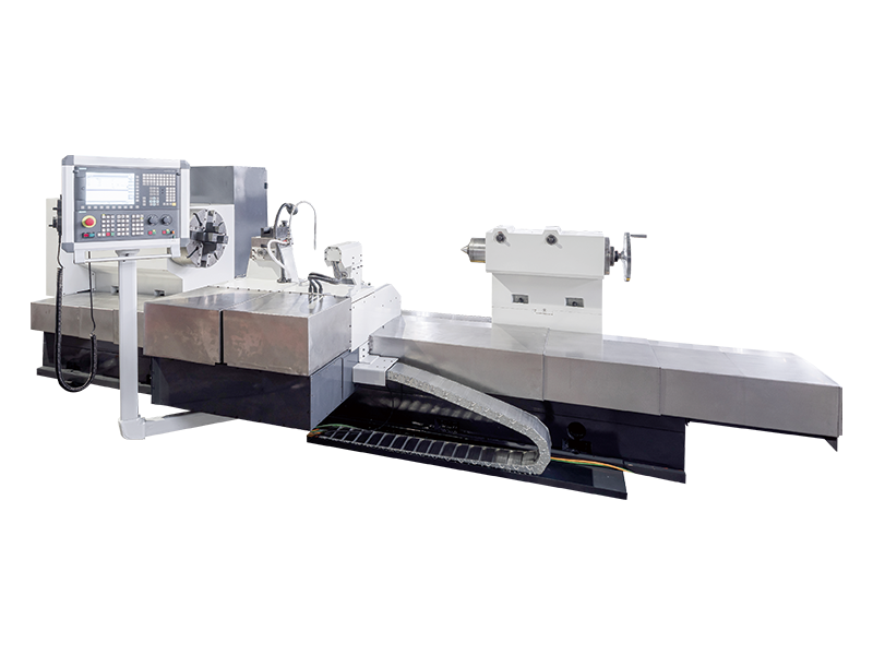
Many industrial rollers are not straight cylinders — they are ground or turned with a deliberately convex crown profile along their length. Crown profiles serve to compensate for the elastic deflection of the roller under load in service, ensuring that the contact pressure between the roller surface and the mating material (paper, metal strip, fabric, or film) remains uniform across the full working width rather than concentrating at the roller's center or edges. The specific crown profile required — whether a simple circular arc, a parabolic curve, or a complex polynomial profile optimized by finite element analysis — must be faithfully reproduced by the CNC machine.
This requirement places specific demands on the CNC system's interpolation capability and on the positioning accuracy of the X axis throughout the full Z-axis travel length. Errors in the executed crown profile — even deviations of a few micrometers from the specified curve — translate directly into non-uniform contact pressure in service, which in printing applications causes color registration errors, in rolling mill applications causes thickness variation in the rolled product, and in paper machine applications causes cross-direction basis weight variation. Evaluating the CNC system's contouring accuracy (not just its positioning resolution) and requesting actual machined crown profile measurement data from the machine manufacturer is an essential step in the selection process for any application where crown profile accuracy is critical.
CNC roller processing machines must handle a wide range of roller materials, each with different machinability characteristics that affect the choice of cutting tools, grinding wheels, speeds, feeds, and coolant systems.
CNC roller processing machines represent a substantial capital investment — from several hundred thousand dollars for a basic CNC roll turning lathe to several million for a large, fully equipped precision roll grinding machine. The investment decision should be evaluated across the full lifecycle cost, not just the purchase price. Key factors beyond the machine specification include the availability and cost of spare parts (particularly spindle bearings, grinding wheel dressing systems, and CNC controller components), the machine builder's service infrastructure in the buyer's region, the quality of operator and maintenance training programs, and the builder's track record with similar applications.
Before finalizing any purchase, request a machining trial on representative workpieces — rollers of the same material, size, and tolerance requirement as those to be produced in production. Measure the trial pieces with independent metrology equipment (not just the machine's own gauging system) to verify that the machine's actual output meets the specified requirements. Review the machine builder's reference list for comparable applications and contact reference customers directly to assess long-term reliability and support responsiveness. A CNC roller processing machine that performs at specification on day one but proves difficult to maintain or support in year three is not a good investment regardless of its initial price.

 Download Material

 E-mail: [email protected]
  Mob: +86-13806297906
  Tel: +86-513-85562198
  Add:No. 99 Tiantong Road, Nantong City, Jiangsu Province.
Factory scene

Copyright@ Jiangsu Dingshun Heavy duty Machine Tool Co., Ltd. All Rights Reserved.




 English
  русский
  Español
  عربى
عربى