
Content
In high-volume metalworking and steel production, two categories of CNC machine represent the boundary between acceptable output and genuinely premium results: the equipment that shapes the tools used in manufacturing, and the equipment that shapes the workpieces those tools then process. CNC roll notching machines and CNC tool grinders occupy exactly these positions — one ensuring that rolling mill rolls carry perfectly dimensioned crescent notches and branding marks for rebar production; the other ensuring that every end mill, drill, and lathe insert used across manufacturing industries is ground to micrometer-level geometry and returned to full cutting performance after wear.
Both machine types share a foundational design philosophy: replace manual skill and accumulated operator error with programmable, repeatable, closed-loop CNC control. Both demand high machine rigidity, precision spindle systems, and sophisticated software. And both are making the transition from specialized niche equipment to standard production infrastructure as tolerances tighten and labor costs rise globally. This guide covers what each machine does, how it works, what specifications matter, and how to select the right configuration for your operation.
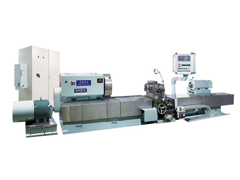
A CNC roll notching machine is a specialized CNC lathe-based system designed to perform a very specific and demanding task in steel rolling mill roll shops: cutting precisely dimensioned crescent-shaped notches — known as ribs or grooves — into the surface of cylindrical rolling rolls, along with branding marks that identify grade, manufacturer, and standard compliance on the finished rebar. The rolls processed on these machines are then installed in rolling mills where they imprint those rib patterns onto hot steel bar, producing the deformed reinforcing bar (rebar) used throughout construction.
Without precisely machined notches in the rolls, it is impossible to produce rebar that meets international dimensional standards. The geometry of the crescent groove — its depth, angle, helix, and spacing — determines directly whether the finished bar achieves the bond strength between steel and concrete that structural engineering calculations depend on. A roll with incorrectly machined notches produces non-compliant rebar, which in markets governed by quality certification cannot be sold. The CNC roll notching machine is therefore not a convenience in a rebar rolling operation — it is the quality-critical process step that certifies the product.
The core architecture of a CNC roll notching machine combines a heavy-duty lathe bed with a specialized milling head mounted on a swiveling saddle. The roll — which may be a high Ni-Cr cast iron roll, a high-speed steel roll, or a tungsten carbide roll ring — is mounted between centers or in a large chuck (typically 500 mm diameter, 4-jaw independent configuration) and rotated by the main spindle. The milling/notching head traverses axially along the roll while simultaneously indexing angularly to cut each crescent groove in sequence.
Modern CNC roll notching machines operate on 4 to 6 controlled axes, with 3-axis simultaneous movement being the standard for notching operations and additional axes enabling the branding/marking function. The typical axis layout is:
The integration of notching and marking in a single machine is a significant productivity advantage — it eliminates a separate clamping and alignment operation that would otherwise be required, reducing total roll processing time and the risk of positional error between notch and mark locations.
CNC roll notching machines are typically controlled by industrial-grade systems — Siemens 808D, Siemens 840SL, or equivalent — operating full servo control on all axes. The operator inputs roll parameters directly: roll diameter, pass radius, number of ribs, rib depth, helix angle, and any rib-skipping requirements. The control system calculates and executes the entire machining sequence automatically. This parameter-driven approach reduces operator skill requirements dramatically compared to manual notching and eliminates the angular calculation errors that are the leading cause of non-compliant notch geometry in manual operations. In the event of a power interruption or tool change during a cycle, advanced controls include a restart-from-breakpoint function that resumes the programmed sequence exactly from the interruption point — critical for minimizing scrap on expensive carbide roll rings.
When evaluating or sourcing a CNC roll notching machine, the following specifications govern whether the machine is capable of handling your roll shop's specific roll range and production requirements:
| Specification | Typical Range | What It Determines |
|---|---|---|
| Max. roll diameter | Ø320 – Ø700 mm | Roll size range the machine can accommodate |
| Max. roll / workpiece length | 500 – 2,500 mm | Maximum pass length and roll body length |
| Rebar size range processed | Ø6 – Ø60 mm bar | Range of rebar products the roll shop can certify |
| Notching spindle power | 2.2 – 7.5 kW | Cutting capability in carbide and HSS rolls |
| Notching spindle speed | 0 – 10,000 RPM | Cutting speed range for different roll materials |
| Time per groove | 10 – 20 minutes (Ø340 mm roll) | Roll shop throughput capacity |
| International standards supported | ISO 6935-2, ASTM A615, BS 4449, JIS G3112, GB1499.2, IS1786, ANSI | Export market reach and certification capability |
| Guideways | Hardened & ground; Turcite-B or linear rolling guides | Long-term positioning accuracy and machine life |
The guideway specification deserves particular attention. Rectangular heavy-bed construction with hardened and ground guideways surfaced with Turcite-B — a low-friction, wear-resistant bearing material — is the foundation of long-term accuracy in roll notching. Machines that compromise on guideway quality will maintain positional accuracy initially but drift significantly over years of heavy-duty roll shop use, producing notch geometry deviations that may not be immediately detected but will eventually result in non-compliant rebar. Rolling linear guide rails on the lateral feed axis reduce friction and support high-speed positioning, but require more stringent contamination protection in the swarf-heavy roll shop environment.
A CNC roll notching machine does not operate in isolation — it is one station in a complete roll shop workflow that includes roll turning, roll grinding, notching and marking, inspection, and storage. Understanding how the notching machine integrates with upstream and downstream processes is essential for sizing the equipment correctly and avoiding production bottlenecks:
Where the CNC roll notching machine serves a defined niche in the steel industry, the CNC tool grinder is a universal precision machine that underpins the performance of cutting tools across every manufacturing sector. A CNC tool grinder — more precisely called a CNC tool and cutter grinder — is a multi-axis CNC grinding machine used to manufacture new cutting tools and resharpen worn ones, restoring them to their original geometry and surface finish with micron-level accuracy.
The tools processed on CNC tool grinders include the full spectrum of rotating and single-point cutting tools: end mills, drills, reamers, taps, step drills, form tools, countersinks, insert blanks, and lathe bits. The geometry of a cutting tool — its rake angles, relief angles, helix angle, core diameter, and edge preparation — determines everything about how it cuts: material removal rate, surface finish quality, tool life, and the forces it generates in the workpiece. A correctly ground tool with optimal geometry outperforms an incorrectly ground equivalent by factors that can reach 3–5× in tool life and 20–30% in cutting speed capability.
Modern CNC tool grinders are 5-axis machines, with some advanced configurations extending to 6 axes for complex tool geometries. The standard 5-axis layout comprises:
Simultaneous interpolation across all five axes in real time is what enables a CNC tool grinder to follow a complex helical flute geometry, maintain a constant clearance angle along a curved cutting edge, or produce the compound angle relationships of a drill point — operations that would take a highly skilled operator hours to execute manually and that the CNC machine completes in minutes with repeatability better than ±5 micrometers (0.0002 inches) on well-maintained machines.
The grinding wheel is the cutting tool of the CNC tool grinder, and its specification is as critical as the machine's axis configuration. The two dominant superabrasive wheel types are:
Advanced CNC tool grinders support multiple grinding wheel sets — typically up to 3 wheels per spindle axis — enabling automatic changeover between roughing, finishing, and polishing wheels within a single program cycle without operator intervention. This automatic wheel management is the key enabler of unattended production in tool grinding.
The software environment of a CNC tool grinder is arguably as important as the mechanical platform. Dedicated tool grinding software — such as NUMROTOplus, ANCA's iGrind, or Walter's HELITRONIC TOOL STUDIO — provides a parametric tool design environment where operators define a tool by its geometric parameters rather than by writing raw CNC code. The software calculates all necessary axis movements, simulates the complete grinding process in 3D with collision detection, and generates the CNC program automatically.
Key software capabilities that separate professional-grade CNC tool grinders from entry-level systems include: 3D simulation with full machine collision monitoring (preventing costly crashes between wheel and workpiece or fixture); automatic in-machine tool measurement using touch-probe or laser gauging (enabling closed-loop compensation for wheel wear without stopping the cycle); and CAD/CAM integration that allows complex custom tool geometries to be designed in third-party software and imported directly into the grinding program. These capabilities collectively enable extended unmanned production — a machine running overnight with automatic tool loading, grinding, measuring, and compensating without an operator present.
| Machine Type | Primary Function | Typical Axis Count | Target Application |
|---|---|---|---|
| 5-Axis Universal Tool Grinder | Full tool manufacture and regrind | 5 | End mills, drills, reamers, form tools — all geometries |
| 6-Axis Tool Grinder | Complex geometry and large tool production | 6 | Hob cutters, large diameter tools, asymmetric geometries |
| High-Volume Production Grinder | Mass production of single tool type | 5 | Drill bits, end mills (1–25 mm diameter range) |
| Insert Grinder | Indexable carbide insert manufacture | 4–5 | Turning, milling, and boring inserts |
| Tool Room / Regrind Machine | In-house tool reconditioning | 4–5 | Mixed tool types, lower volume, flexible operation |
Selecting the right CNC tool grinder requires evaluating specifications against the actual tool range you intend to produce or recondition. The following parameters are the most consequential:
While the two machine types serve different primary industries, their combined reach spans virtually the entire manufacturing economy:
The two machines covered in this guide occupy clearly defined positions in the manufacturing equipment hierarchy, and their selection criteria reflect their distinct operational contexts:

 Download Material
 E-mail: [email protected]
  Mob: +86-13806297906
  Tel: +86-513-85562198
  Add:No. 99 Tiantong Road, Nantong City, Jiangsu Province.
Factory scene

Copyright@ Jiangsu Dingshun Heavy duty Machine Tool Co., Ltd. All Rights Reserved.


 English
  русский
  Español
  عربى
عربى 


